RC electronics troubleshooting: a practical step-by-step guide
This tutorial sets out a clear, methodical approach to RC electronics troubleshooting for model aircraft, cars and boats, aimed at makers who prefer a measured process over guesswork. The instructions assume basic experience with soldering and handheld tools, and focus on identifying faults in power, signal and servo systems before replacing expensive components. The goal is to find the simplest fix first and to document findings so problems do not recur.
Before you begin, gather the right tools and take basic safety precautions. You will need a reliable multimeter, a servo tester or bench receiver, spare servo leads and connectors, a small soldering iron, heatshrink and cable ties, and insulated pliers. Work in a well ventilated area away from fuel or flammable materials, remove propellers or wheels from powered models, and disconnect batteries until you are ready to test with controlled power. Always treat lithium batteries with respect and never leave them charging unattended.
- Check battery voltage and connector condition before anything else to avoid damaging electronics.
- Inspect wiring and connectors for chafing, pin corrosion or reversed polarity when plugging connectors back in.
- Ensure the receiver antenna is intact and routed away from power wires to reduce interference.
- Use a servo tester to confirm basic servo movement separately from the radio system.
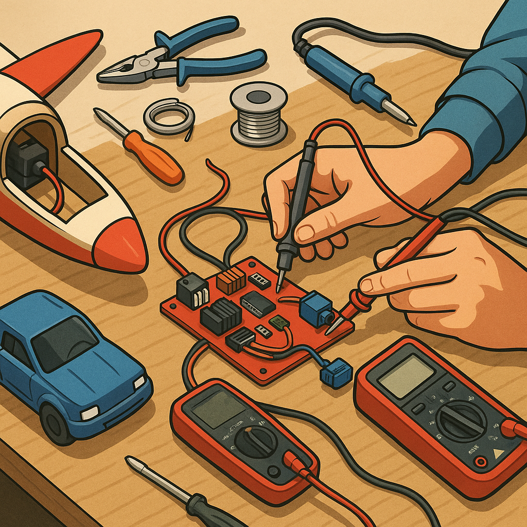
Start the troubleshooting sequence with a visual inspection and power verification. Look for burnt components, lifted PCB tracks, swollen capacitors or cracked solder joints around the ESC and receiver. With the battery disconnected, wiggle each connector and press down on crimp joints to reveal intermittent faults. Reconnect the battery briefly and measure voltage at the receiver and at the ESC power input to confirm the expected voltage and the presence of the BEC output if applicable. If voltages are absent or significantly below nominal, investigate battery health and connector wiring as the primary suspects.
Next, isolate the signal chain to pinpoint where control inputs stop. Use a dedicated servo tester or a bench receiver bound to your transmitter to test each servo independently. Remove servos from linkages and confirm full travel and neutral position. If a servo behaves erratically when connected to the model but fine on the bench, suspect interference, wiring faults or mechanical loading. Measure PWM or serial signal output at the receiver pins if you have access to an oscilloscope, otherwise swap channels to see if the fault follows a channel or stays with a device.
Focus on ESC and motor checks if the power system is the issue. Run an ESC bench test with the propeller removed and apply low-throttle inputs to verify smooth motor start and consistent idle. Listen for unusual sounds or stuttering that indicate motor winding damage or commutation problems in brushless motors. Check the ESC programming settings and ensure the correct timing mode and battery cell count are selected. If the ESC has a separate BEC, confirm that its regulated output is stable under load, and consider using a low-dropout BEC or a separate regulator if voltage sag is observed during heavy current draw.
Address receiver and radio-system issues by confirming binding, range and fail-safe behaviour. Rebind the receiver to the transmitter following the manufacturer's procedure and test range on the ground with the model restrained. Reposition the antenna away from metal or high-current wiring and avoid running antenna parallel to motor leads. If telemetry or digital protocols are used, ensure both ends support the same data format and check for firmware updates where applicable. Intermittent faults often point to poor antenna connection or damaged pins in a connector. For more builds and experiments, visit my main RC projects page.
Conclude with systematic isolation and replacement to resolve stubborn problems and document what you tried. Replace suspect servo or ESC with a known-good unit to confirm a fault rather than continuing to guess. Keep a short log of symptoms, test steps and voltages so you can reverse changes and learn from the fault. If you want more Maker & DIY project guides and reference articles to support repairs, visit the Maker & DIY category. If a problem persists after these steps, consult the manufacturer or community forums and consider seeking professional repair for complex powertrain damage.
Comments
Post a Comment