3D printing for functional parts: a troubleshooting guide
Functional parts demand a different mindset to decorative prints, because they must withstand loads, fit other components and keep tolerances over time. Practical troubleshooting begins with design choices and material selection, and continues through printer calibration, slicer settings and post-processing. This guide focuses on recurring issues makers encounter when printing serviceable components on common FDM machines and offers concrete checks and fixes you can apply at each step.
Material choice drives many failures, so start by matching filament to function rather than convenience. PLA is easy to print and good for low-stress prototypes, PETG offers better toughness and chemical resistance, ABS and Nylon handle heat and wear but need enclosures and dry filament, and polycarbonate is best for high-strength parts but requires high temperatures. If you want more project ideas or design tips in the same maker space, see the Maker & DIY tag on this site for related posts that share practical setups and profiles.
Poor bed adhesion and warping are among the most common causes of failed parts, especially for large or flat geometries. First-layer height and extrusion rate are critical, so calibrate Z-offset until the initial line is slightly squashed and consistent. Use a heated bed at manufacturer-recommended temperatures — for example, 200–210°C nozzle with 50–60°C bed for PLA, 240–260°C nozzle with 70–100°C bed for PETG or ABS as appropriate — and consider a brim for parts with small footprints or sharp corners. Clean the bed surface and use adhesives such as PVA glue stick or specialised print surfaces when necessary, and add an enclosure for temperature-sensitive materials to reduce thermal gradients.
Layer adhesion and part strength often seem random but are usually resolvable by looking at print orientation and wall settings. Orient parts so the primary load does not act across layer interfaces where tensile strength is weakest, and increase wall count or shell thickness to shift load-bearing to perimeter walls. Slightly higher nozzle temperatures can improve interlayer diffusion, but avoid overheating which causes sagging or dimensional drift. Consider increasing extrusion multiplier by small increments if layers appear under-bonded, and use larger nozzle diameters or coarser layer heights when strength is prioritised over fine detail.
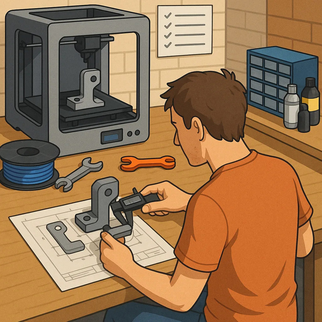
Dimensional accuracy problems are often due to calibration, slicer compensation or shrinkage of the chosen polymer. Measure printed test cubes and adjust steps-per-millimetre for each axis if needed, and calibrate flow rate by printing thin-walled cylinders to confirm wall thickness. Verify belt tension and pulley grub screws, and check for play in linear rods or bearings that can introduce wobble. Slicer settings such as horizontal expansion, retraction and overlap can affect fit, so iterate with simple test fittings rather than full parts until the fit is satisfactory.
Common print defects include stringing, under-extrusion, and occasional blobs that compromise function, and these usually have straightforward fixes. Stringing responds to reduced nozzle temperature and optimised retraction settings, while under-extrusion can come from clogged nozzles, worn drive gears, moisture in filament or incorrect feeder tension. Check for filament grinding marks, clear partial clogs by cold-pulling or replacing the nozzle, and dry hygroscopic materials such as Nylon before printing. Regular maintenance of the extruder and Bowden tube connections prevents many intermittent issues.
- Quick pre-print checklist: confirm filament dry and loaded correctly.
- Check nozzle and bed temperatures match filament recommendations.
- Verify Z-offset with a test skirt or single-layer square.
- Confirm belts and screws are tight and the machine is free of play.
- Run a small calibration print for dimensional checks before a large job.
Post-processing and validation are part of reliable production. Consider annealing some materials to improve heat resistance and creep performance, and use mechanical joining methods such as solvent welding, M3 inserts or bolts where appropriate to reinforce weak features. Surface finishing like sanding and tumbling can remove stress concentrators that lead to crack initiation. Finally, document the successful combination of material, orientation and slicer profile so you can repeat it reliably and iterate small design changes based on measured test results rather than guesswork. For more builds and experiments, visit my main RC projects page.
Comments
Post a Comment