3D printing for functional parts: a pragmatic step-by-step tutorial.
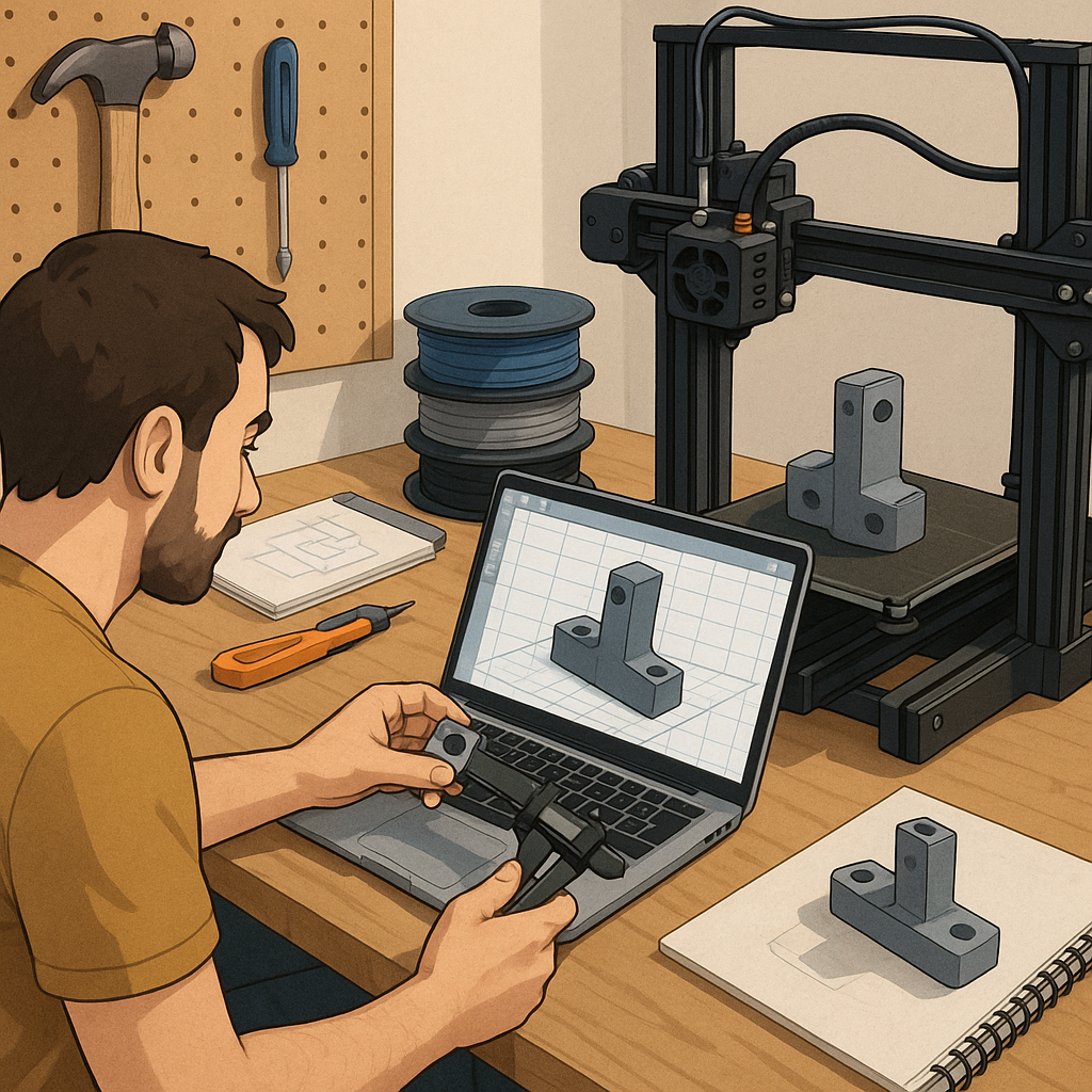
This tutorial walks through a practical workflow to design, print and test functional parts using FDM 3D printing, aimed at makers who want reliable, repeatable results rather than decorative prints. I assume you have a basic desktop FDM printer, a slicing programme and some common filaments such as PLA, PETG and ABS. The focus is mechanical behaviour, fit and durability, so each step emphasises choices that affect strength, tolerance and longevity. Follow the sequence rather than skipping to avoid common mistakes that force redesigns or waste filament. The steps cover material selection, CAD considerations, orientation and slicing, test printing, post-processing and verification before final use.
Start by gathering materials and the right tools for measuring and assembly, because preparation reduces iteration time. Choose the filament by intended use: PLA for prototyping and low-stress parts, PETG for impact resistance and mild heat, ABS for high-temperature applications if your printer and enclosure support it. Recommended basic tools and consumables include a vernier caliper, a digital thermometer probe for the nozzle, spare nozzles in 0.4 mm and 0.6 mm sizes, a set of taps and nuts for metal inserts, and appropriate adhesives for bonding and sealing.
- Vernier caliper for measuring critical dimensions and clearances in millimetres.
- Spare 0.4 mm nozzle and a coarser 0.6 mm nozzle for faster structural prints.
- Taps and heat-set inserts for threaded joints and metal fasteners.
- Glass or PEI print surface to improve first-layer adhesion and flatness.
- Sanding paper, files and a hobby knife for post-process finishing.
Design parts in your CAD package with functional geometry and manufacturing constraints in mind, and plan tolerances before exporting STL files. For sliding fits, allow 0.2 to 0.4 mm clearance depending on print precision and filament, and for press fits allow 0.1 to 0.2 mm negative clearance if you expect to trim or sand the part. Add fillets to distribute stress around holes and corners, avoid long thin unsupported walls, and design sacrificial alignment features to help assemble components. For threaded connections consider using standard metric screws with clearance holes or incorporate heat-set inserts to avoid stripping plastic under repeated torque, and design test coupons to validate these features before committing to a full batch.
Orientate and slice the part to put tensile loads parallel to layer lines where possible, since layer adhesion is usually the weakest direction in FDM parts. Typical slicing settings to start with are 0.2 mm layer height for a balance of speed and strength, two to four perimeters depending on wall thickness, and an infill of 20 to 40 percent for moderate strength or up to 100 percent for load-bearing cores. Use slower speeds of 30 to 50 mm/s for increased strength, set nozzle temperature according to filament: PLA 200 to 215°C, PETG 230 to 250°C, ABS 230 to 250°C, and bed temperatures PLA 50 to 60°C, PETG 70 to 90°C, ABS 90 to 110°C. Enable cooling for PLA, reduce fan for PETG, and avoid fan for ABS to prevent warping, and enable proper retraction to reduce stringing on fine features.
Print a small set of test coupons to validate dimensional tolerance, layer adhesion and surface finish before printing the final part. A calibration cube, a 20 mm diameter hole test, and a small cantilever or tensile strip will reveal whether you need to adjust temperature, flow rate or print speed. If holes are undersized, try increasing hole diameter in CAD by 0.2 to 0.5 mm or ream them out after printing using a drill or reamer. For embedded nuts or inserts, either pause the print and insert hardware at the correct layer or use heat-set inserts driven in after printing with a soldering iron to provide a durable threaded connection. Record the successful settings for each filament so you can reproduce results consistently.
Post-process and test the finished part using mechanical checks relevant to its application, such as torqueing fasteners to the intended spec or fitting moving parts together and running them through their range of motion. Light sanding and chamfering mating edges improves fit and reduces wear, and annealing certain filaments can increase heat resistance and reduce internal stresses by heating printed parts gradually to the material-specific temperature and cooling slowly. Conduct at least one real-world trial under safe conditions and inspect for cracks, excessive deformation or chemical attack, and iterate the design and print settings as needed. For more project ideas and practical examples in this area, see the Maker & DIY tag on this site for similar workflows and templates to adapt to your own builds. For more builds and experiments, visit my main RC projects page.
Comments
Post a Comment