RC electronics troubleshooting: practical tips and tricks for makers
RC electronics troubleshooting is a mix of methodical diagnosis and practical hands-on fixes, and this guide collects tips suited to makers and hobbyists who want reproducible results. Start with the mindset that almost every fault has a cause that can be isolated with the right tools and orderly testing, and avoid swapping parts at random unless you are collecting baseline data. Document what you try as you go so that you can undo changes and learn patterns that repeat across models and systems.
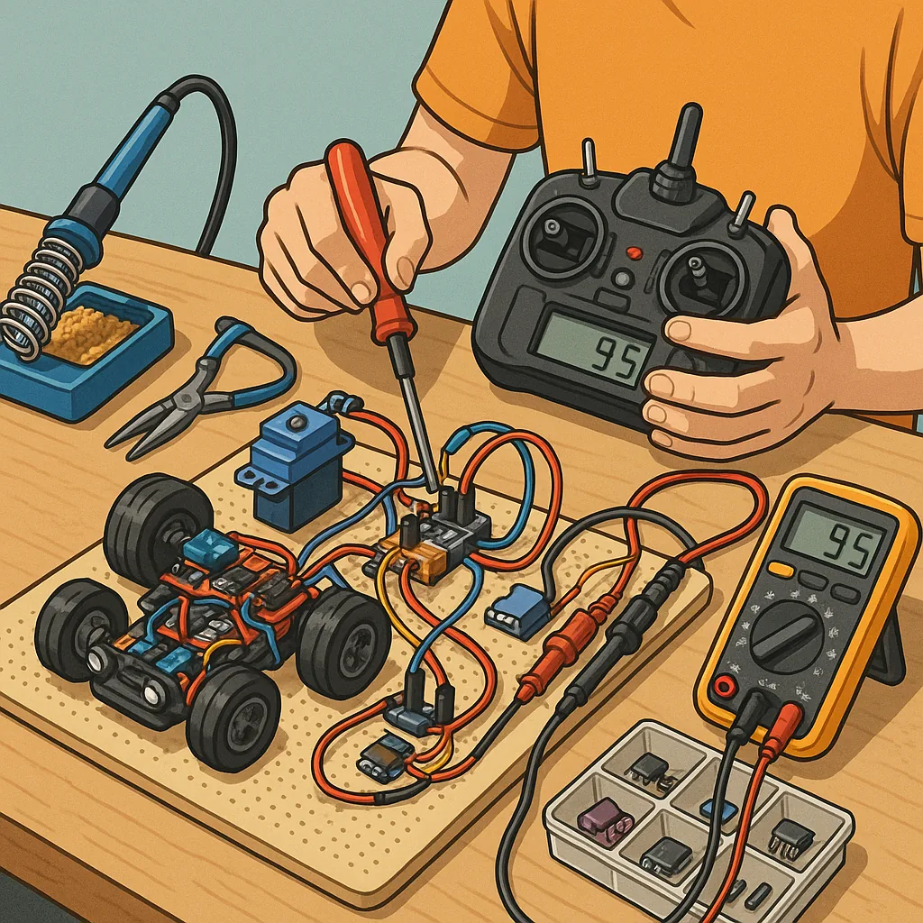
- Digital multimeter with current clamp or separate current meter for under-load checks.
- Portable oscilloscope or logic analyser for signal checks and PWM inspection.
- Servo tester and bench power supply to run components off-system.
- Soldering iron, desolder braid, flux, and spare connectors for repairs.
- Spare ESC, receiver, servo and short lengths of wire for substitution testing.
Begin with a simple checklist that catches the most common issues before deep-diving into electronics. Confirm that the battery is healthy and properly charged and check voltage at the system rails with the components connected so you see the under-load behaviour. Inspect connectors and leads for corrosion, crushed pins, or cold solder joints, and reseat or replace suspect plugs. Verify correct polarity at battery and ESC connections to avoid damage, and always secure loose wiring to prevent intermittent shorts caused by vibration.
For power system problems focus on voltage stability, BEC output and current draw. If motors or servos stall and the voltage sags, measure the battery voltage under load rather than open-circuit voltage, as a bad pack can read healthy with no load. Check the ESC’s BEC or UBEC for overheating and voltage drop, and consider using a separate UBEC for high-current radio systems. Add decoupling capacitors at motor leads if noise is a recurring issue, and ensure ESC programming matches your motor type and battery cell count.
When dealing with radio link and receiver faults, treat binding and antenna placement as prime suspects. Re-bind the receiver to the transmitter and verify failsafe settings so the model behaves predictably if signal fails. Make sure receiver antennas are routed away from noisy components such as ESCs and brushless motors, and test with another transmitter or a known-good receiver to rule out transmitter glitches. Use a bench receiver with telemetry or an LED status indicator to determine if packet loss is due to RF environment or receiver hardware.
Servos and mechanical issues present symptoms that look electronic but are actually mechanical in origin, so check for stiction, stripped gears and excessive friction before condemning the servo electronics. Listen for intermittent buzzing or clicking which often signals binding or overload rather than a failed PCB. Measure servo current with a clamp or inline meter while moving through the full range; sustained high current at one end usually indicates a mechanical obstruction or misadjustment rather than an electrical fault.
Intermittent faults require patience and a systematic approach because they can be caused by vibration, temperature, or marginal solder joints. Stress-test the system by running it under conditions close to real use, and gently manipulate wiring and connectors while observing behaviour to reproduce the fault. Protect vulnerable joints with strain relief and heatshrink, and treat corroded components with contact cleaner followed by conformal protection if the model will see humid or salt-air conditions.
Adopt a clear workflow to reduce time spent chasing ghosts: recreate the fault on the bench, isolate the subsystem, substitute known-good components, and log results. Keep a small bag of common spares and a labelled cable harness to speed substitution testing, and use simple tools such as a servo tester or a bench power supply to provide a controlled environment. If you want more projects and detailed write-ups that relate to these techniques visit the Maker & DIY archive for similar guides and build notes at Build & Automate's Maker & DIY label.
Finally, treat repairs as learning opportunities and prioritise fixes that restore safe operation rather than cosmetic perfection. Replace components that show signs of thermal stress or repeat failure, and keep firmware and ESC settings documented so you can rebuild a tested baseline quickly. With a small kit of tools, a logical process and a habit of documenting findings you will reduce downtime and improve the reliability of your RC models over time. For more builds and experiments, visit my main RC projects page.
Comments
Post a Comment