ESP32 beginner projects: a practical troubleshooting guide for common issues
This troubleshooting guide is aimed at anyone starting ESP32 beginner projects who hits common roadblocks during setup and early development. I will focus on practical checks and fixes you can apply at the bench without specialist tools, and on diagnostic steps to narrow down faults quickly. The suggestions assume a hobby development board such as a WROOM or WROVER module on a USB board, but many points apply to custom PCBs too.
Start with the basics of connectivity and tools because the majority of problems are simple to fix. Use a known-good USB cable that supports data transfer rather than a charge-only cable, and try different USB ports on your computer. Confirm the board shows up as a serial device in your operating system and that you have installed the correct USB-to-UART drivers for chips such as CP210x or CH340. In your IDE select the correct ESP32 board variant and the matching COM port or device path, and set the serial monitor to the right baud rate often 115200 for initial logging.
Flashing failures are a frequent stumbling block when starting on ESP32 beginner projects and typically present as timeouts or “failed to connect” messages from esptool. Check whether the board needs to be put into bootloader mode manually by holding the BOOT or IO0 pin low while resetting, and ensure EN (enable) and IO0 pins are not pulled by extra circuitry on your prototype. Try different flash settings in the IDE, lower the baud rate for more reliable uploads, and temporarily disconnect sensors, displays or I²C/SPI lines that might interfere with the boot sequence during programming.
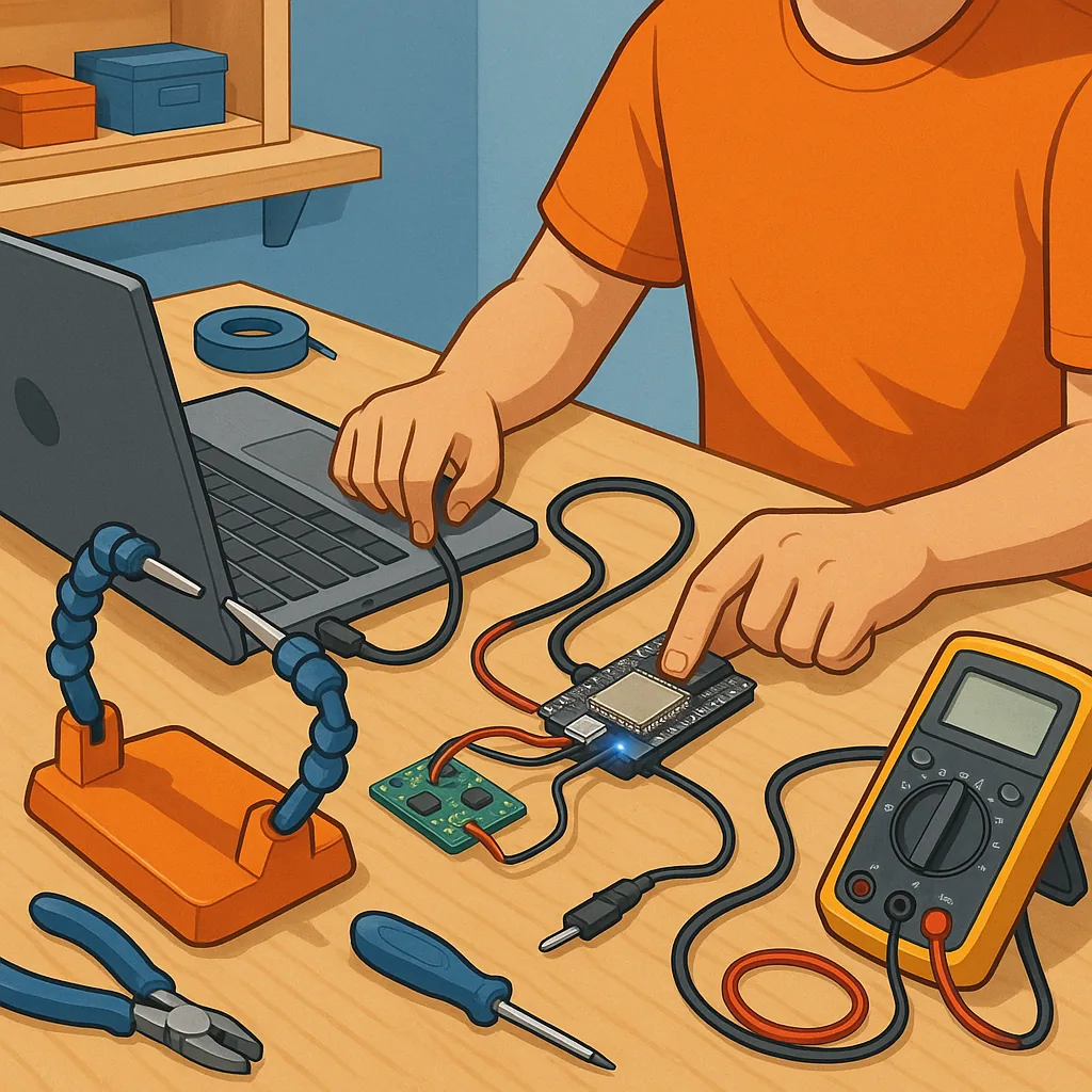
Power issues are responsible for many odd behaviours and intermittent reboots on ESP32 boards used in beginner projects. The ESP32 can draw significant current during radio transmission spikes, so a weak USB supply, poor cable or a low-quality regulator can cause brownouts and resets. Measure the voltage at the board under load with a multimeter, look for the brownout message on the serial monitor, and add decoupling capacitors or an external 3.3V regulator if needed. If your project uses peripherals that draw additional current, consider separate power rails with a common ground and avoid powering high-current devices from the 3.3V pin on the USB adapter alone.
Wiring and pin selection are common sources of frustration in ESP32 beginner projects because some GPIO pins have special boot-strapping roles. Avoid using strapping pins such as GPIO0, GPIO2, GPIO15 and MTDI for critical outputs that alter state during reset, and do not expect 5V tolerance on inputs marked for 3.3V logic. When using ADC channels or touch sensors be mindful of noise and floating inputs, and use proper pull-ups or pull-downs. Document the pins you use so you can quickly revert to a minimal configuration when debugging boot or stability problems.
WiFi and networking problems can look like hardware faults but often stem from configuration or environment. Confirm the ESP32 logs show attempt to connect and whether DHCP gives a valid IP address, and watch for connection watchdogs or memory allocation failures in the serial output. If the device connects but has intermittent drops, check router settings, channel congestion and region settings, and try a static IP for predictable behaviour while debugging. For OTA updates, ensure timeouts are long enough and test on the local network before exposing the device to cloud services.
- Quick checklist: confirm USB cable and port, install drivers, select correct board and COM port, lower baud for flashing, disconnect peripherals during programming, measure supply voltage under load, avoid strapping pins, check serial logs for brownout or boot messages, and restart with a minimal sketch.
When a problem persists adopt a methodical approach: reduce the project to the simplest working example, substitute known-good components such as another ESP32 board or power supply, add serial logging liberally to find the failure point, and then reintroduce parts one at a time. Keep notes of the changes you make so you can reproduce fixes and understand intermittent faults. For more hands-on articles and project notes you might find the Maker & DIY label useful for related techniques and examples, see https://build-automate.blogspot.com/search/label/Maker-DIY. For more builds and experiments, visit my main RC projects page.
Comments
Post a Comment