3D printing for functional parts: a step-by-step tutorial.
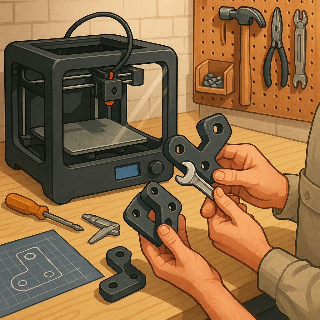
Making functional parts with a desktop 3D printer is a practical way to solve problems around the workshop and prototype new ideas before committing to machined or injection‑moulded production. This guide walks through the process from design to testing with clear decisions at each step so you can reliably produce parts that fit, function and survive expected loads. It assumes you have a fused filament fabrication printer but many principles apply to resin or industrial machines, and I aim to keep recommendations conservative to improve first‑print success rates and reduce waste.
Step 1 is design and engineering for additive manufacture, and it starts with knowing the function and the environment where the part will operate. Capture dimensions, tolerances and expected loads, then design with features that suit layer‑by‑layer construction such as filleted corners, chamfers to reduce stress concentrations and thicker walls where fastenings or bearings will go. Avoid thin unsupported cantilevers and design clearance for fasteners rather than relying on exact dimensional accuracy from the first print. If possible create a parametric model so you can quickly iterate dimensions during testing.
- Tools and materials: printer, calibrated bed, spare nozzles, digital calipers, files and sandpaper, appropriate filament (PLA, PETG, ABS, Nylon or polycarbonate) and adhesives where needed.
- Software: CAD for modelling, slicer for generating G‑code, and a small test rig or simple fixtures for functional testing.
- Consumables: glue stick or PEI sheet for adhesion, isopropyl alcohol for cleaning and gloves for handling hot or chemical processes.
Step 2 covers material choice and slicer settings which determine strength more than appearance. Choose a material that matches the thermal, chemical and mechanical demands of the part; PETG is a good all‑round option for strength and ease of printing, ABS or polycarbonate for higher temperature resistance, and nylon for abrasion and fatigue resistance. Set layer height between 0.1 and 0.3 millimetres depending on required detail and strength, and increase wall/perimeter count to at least three for load‑bearing parts. Use a higher infill percentage and consider grid or gyroid patterns for isotropic internal structure when strength is important.
Step 3 is orientation, supports and print settings that affect mechanical performance. Orient parts so layers run perpendicular to the primary load direction to avoid delamination, or design interlocking features that distribute stress across layers. Minimise overhangs greater than about 45 degrees to reduce support material and post‑processing, and place supports strategically where they are easiest to remove. Calibrate flow rate, print temperature and cooling to ensure good inter‑layer adhesion without stringing, and consider a thicker first layer and brim or raft for parts with small footprints to prevent warping.
Step 4 is post‑processing and testing which turns a printed object into a verified component. Remove supports carefully with appropriate tools, then use sanding, solvent smoothing or fillers if you need tight sealing surfaces. For thermoplastics such as ASA or PETG you can improve strength and heat resistance with controlled annealing following manufacturer recommendations, and epoxy impregnation or bonding often improves bearing surfaces and adds fatigue life. Perform a simple test regime that checks dimensional fit, functional loads and a few cycles of use before full deployment, and record settings and outcomes so you can reproduce successes. For more builds and experiments, visit my main RC projects page.
Step 5 is iteration and maintenance, essential parts of any maker process where the first print rarely meets final requirements. If a part fails, analyse the failure mode and modify print orientation, increase wall thickness, swap filament or add fillets to reduce stress points, then reprint and re‑test until performance is consistent. Keep a small log of filament batches and printer calibration values to track changes over time, and store finished parts away from UV and extreme heat where material properties may degrade. For more project ideas and practical guides in the same category see the Maker & DIY tag.
Comments
Post a Comment