ESP32 beginner projects: three simple step-by-step builds to get started
This guide walks you through three practical ESP32 beginner projects and gives clear step-by-step instructions that suit a maker or DIY enthusiast who is new to the board and its ecosystem.
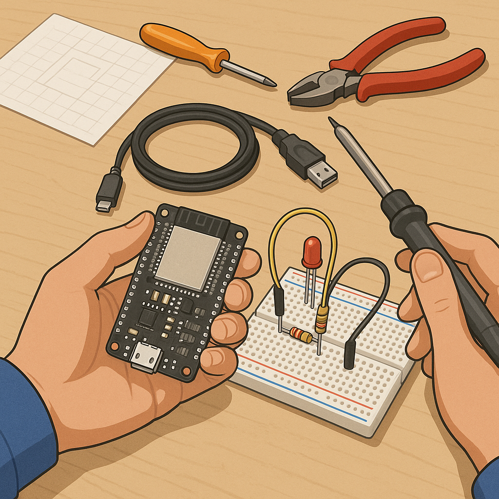
- ESP32 development board (e.g. DevKitC or WROOM variant).
- USB cable for programming and power.
- One LED and a 220 ohm resistor for the blink project.
- One DHT22 or DHT11 temperature and humidity sensor with jumper wires for the sensor project.
- Breadboard and jumper wires for wiring and prototyping.
- Access to a WiFi network for the web server project.
Step 1 is to prepare your software environment and drivers so that you can upload sketches to the ESP32 in a reliable way, and the simplest route is the Arduino IDE for beginners because of its familiarity and wide library support, and because it reduces friction when you first try example sketches.
To set up the Arduino IDE, open the IDE and add the ESP32 boards manager URL in the preferences, then open the Boards Manager, search for ESP32 and install the Espressif package, finally select your specific ESP32 board from the Tools menu and choose the correct serial port, and install CP210x or CH340 drivers if the board is not recognised by the host computer.
Project 1 — Blink an LED: wire the LED anode to a digital pin such as 2 through the 220 ohm resistor and the cathode to ground, or use the built-in LED on many development boards which is already connected to GPIO2, then create a new sketch and write a simple setup that sets the pinMode to OUTPUT and a loop that toggles the pin with delay(500) between HIGH and LOW, save the sketch, select Upload in the IDE and watch the LED blink when the upload finishes and the board resets.
Project 2 — Read temperature and humidity: connect the DHT sensor data pin to a free digital pin, add power and ground, then install the DHT sensor library from the Library Manager in the Arduino IDE and open the DHT example, set the correct sensor type and pin in the sketch, upload the code and open the Serial Monitor at the configured baud rate to see regular readings appear, and use those values to learn about polling intervals, sensor reliability and simple conversion or calibration if your readings seem offset.
Project 3 — Simple web server to control the LED: start from a basic WiFi example, include WiFi.h, set your SSID and password constants in the sketch, in setup() connect to the network and print the assigned IP address to the Serial Monitor, create a small HTTP server that listens for GET requests and toggles the LED state when a specific path is requested, upload the sketch, open the printed IP address in a browser on the same network and use the simple control page to switch the LED on and off, and consider adding simple logging to Serial to help with debugging connectivity issues.
Troubleshooting tips and next steps: if uploads fail, check the correct COM port and board selection, press the boot or EN button on the board while starting an upload sometimes helps, if serial output is noisy ensure you have the right baud rate, and if WiFi does not connect check SSID and password for typos and that your network supports the board frequency, and when you are comfortable with these three projects you can combine them, for example sending sensor data to the web server or to a local MQTT broker for home automation experiments, and if you want more help or project ideas you can visit the Maker & DIY tag on this blog at Maker & DIY tag on this blog. For more builds and experiments, visit my main RC projects page.
Comments
Post a Comment