RC electronics troubleshooting: practical tips for makers and DIYers.
Troubleshooting RC electronics is a task best approached methodically, and this guide collects practical tips and tricks that work in a small workshop or at the flying field. Start with simple, repeatable checks and build evidence as you go. Avoid swapping parts at random, because that can mask intermittent faults and waste time. Safety matters: remove props, disconnect batteries before major work, and be ready to isolate systems if a short or overheating occurs.
Begin with the basics that account for most failures, namely power supply, connectors and physical damage. Check battery voltage with the system under load, and confirm connector polarity and integrity. Inspect solder joints for cracks, cold solder, or lifted pads, and look for corrosion on plugs and sockets. For removable modules such as receivers and ESCs, re-seat them and test on a bench supply when possible. Keep a simple log of what you test so you do not repeat the same checks unnecessarily.
Wiring and power distribution often hide subtle faults that show as intermittent behaviour or reduced performance. Measure continuity on each rail and verify voltage at the point of load because voltage drop across thin wires or bad connectors causes brownouts. Pay attention to the ESCs’ BEC output and whether multiple BECs are paralleled, which can cause conflicts. Look for heat-stressed components or swollen capacitors as signs of overload, and smell for burnt insulation as an indicator of a failing component. Where possible, swap a suspect battery with a known-good unit to isolate the problem to power or the load.
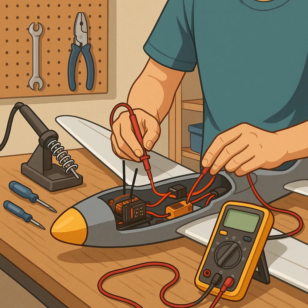
- Confirm battery voltage under load using a multimeter or data logger to reveal voltage sag that a static check may not show.
- Perform a servo sweep to check full travel and detect binding or jitter that suggests mechanical or signal issues.
- Check receiver binding and antenna position for radio problems rather than assuming the servos are faulty.
- Listen for ESC beeps on power-up to confirm channel mapping and throttle calibration are correct.
- Inspect ground commonality between modules to avoid floating references causing erratic behaviour.
- Use short, labelled jumper leads to make temporary connections for proof-of-concept testing.
Signal and RF troubles demand different tactics than power faults because symptoms appear as loss of control, range reduction, or jitter. First, try a range test in an open area with the model tethered or restrained. Swap to another receiver or transmitter if you suspect a module, and check antenna integrity and routing to avoid shielding by carbon or metal parts. Consider environmental interference from nearby transmitters or electrical noise from high-current ESCs and motors; add ferrite beads or re-route wires to reduce common-mode noise where necessary. Review failsafe and telemetry settings to ensure predictable behaviour under signal loss.
Good tools and a disciplined workflow make troubleshooting faster and more reliable. Carry a reliable multimeter, a bench power supply with current limiting, a simple servo tester, and a small logic probe or oscilloscope if you work with serial telemetry or PWM signals. Label wires during disassembly, photograph layouts before you remove components, and return parts to a known-good configuration after each test. If a component repeatedly fails post-repair, favour replacement over repeated rework to save time and reduce risk. For further project ideas and community contributions on Maker & DIY topics, see the Maker & DIY tag on this blog at Build & Automate's Maker & DIY posts. For more builds and experiments, visit my main RC projects page.
Comments
Post a Comment