3D printing for functional parts: a practical checklist guide
3D printing for functional parts is about turning a digital idea into a component that performs reliably in the real world. This checklist guide focuses on decisions you must make before you start printing, covering design, material choice, printer setup, post-processing and testing. The goal is a concise, repeatable workflow that reduces trial and error and produces parts that meet strength, fit and durability requirements. Whether you are producing jigs, brackets, replacement gears or enclosures, these steps will help you avoid common mistakes and make better use of machine time and material resources.
Begin with design fundamentals and tolerances. Consider the function of the part first and sketch the load paths, contact points and interfaces with other parts. Specify critical dimensions and tolerances rather than assuming the printer or slicer will automatically deliver them. Design for layer direction by aligning strength-critical features parallel to layers where appropriate, and include fillets and chamfers to avoid stress concentrations. Think about assembly: add clearance for fasteners and mates, and decide whether features should be printed or added later as inserts. Use parametric design where possible to make iterative adjustments quicker.
Choose the right material for performance and manufacturability. PLA is useful for prototypes and low-stress parts but is unsuitable for high-temperature or load-bearing applications. PETG and ABS provide better toughness and heat resistance, while nylon and polycarbonate are the options for demanding mechanical applications. Consider composite filaments with carbon fibre or glass fibre for stiffness, but be aware of increased abrasiveness and possible nozzle wear. Also weigh environmental factors such as UV exposure, chemical contact and moisture absorption when selecting a filament, and remember that joint design and part geometry can be as important as the base polymer.
Set up your printer and slicer for consistent results. Calibrate extrusion multiplier, flow rates and e-steps before attempting functional parts. Use a nozzle diameter and layer height that balance precision and strength, noting that thicker layers and larger nozzles can increase bonding between roads but reduce surface detail. Optimise print orientation to reduce unsupported overhangs and to align layers with primary load paths. Adjust infill pattern and percentage for stiffness and weight, and tune shell thickness and top/bottom layers to protect against shear and impact. Check bed adhesion and consider using a heated bed, adhesive aids or specialised build surfaces for high-temperature materials.
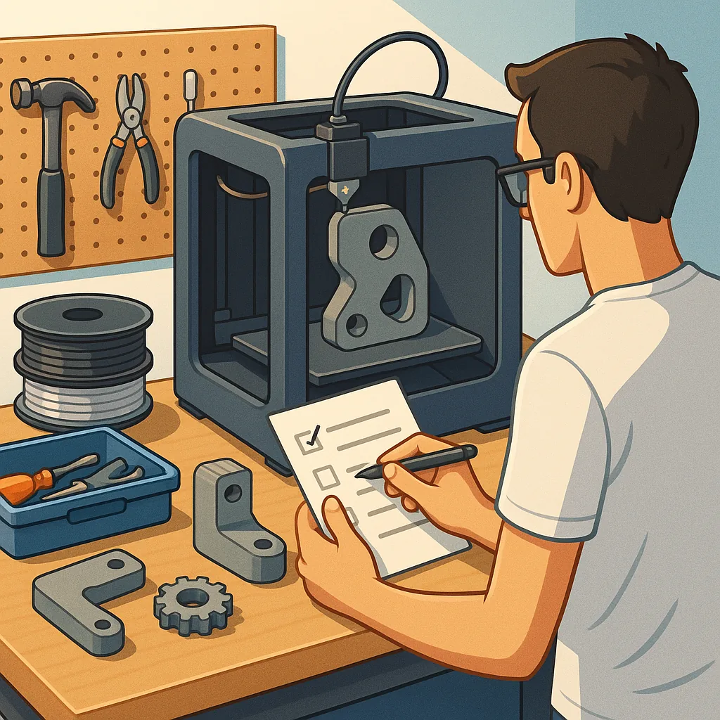
- Define the part's functional requirements including load, environment and lifespan before printing.
- Choose a material that matches mechanical and thermal needs while considering printability.
- Calibrate the printer for dimensional accuracy and flow consistency prior to production.
- Orient the part to align layers with stress directions and to minimise support structures.
- Set wall thickness and infill to achieve the necessary strength without unnecessary weight.
- Plan for assembly features such as snaps, bosses or threaded inserts in the design stage.
- Include a testing and iteration step to validate fit and function before finalising the design.
Post-processing transforms a printed object into a truly functional component. Mechanical finishes such as filing, sanding and drilling are useful for fit adjustments, while chemical smoothing can improve sealing and reduce stress risers on some polymers. For improved mechanical properties, annealing can increase crystallinity and thermal resistance for polymers that tolerate heat treatment, but test on sample pieces as warping or distortion is possible. Consider heat-set threaded inserts or helicoils for repeated assembly cycles, and use adhesives or epoxy in joints where appropriate. Always remove support material carefully to avoid damaging thin features.
Test parts under real conditions and inspect for failure modes. Start with dimensional verification using callipers, then perform functional trials at increasing loads while monitoring for creep, delamination and brittle failure. Use simple test rigs or fixtures to reproduce typical forces and check mating parts for wear and clearance changes. Record settings and results so you can reproduce successful prints later, and keep a note of failed iterations and the adjustments that corrected them. Controlled testing shortens the development cycle and prevents small undetected weaknesses from causing larger system failures.
Common pitfalls include relying solely on default slicer settings, underestimating environmental impacts, and skipping calibration steps. Poor layer adhesion often traces back to inappropriate temperatures or too-fast print speeds, while dimensional drift usually indicates extrusion or e-step errors. Remember that stronger infill does not always replace structural design; well-placed ribs and fibres often outperform simply increasing infill percentage. For further project ideas and practical examples in the Maker & DIY category you can browse recent posts that demonstrate these techniques in action by visiting the tag page at Maker & DIY on Build & Automate. For more builds and experiments, visit my main RC projects page.
Comments
Post a Comment