Troubleshooting guide for basic soldering and wiring reliability.
This troubleshooting guide covers what to check when a hand‑made board, a wire bundle or a connectorised loom fails to behave as expected, with a focus on basic soldering and wiring reliability rather than advanced manufacturing techniques. Start with a calm, systematic approach: replicate the fault if possible, isolate the sub‑assembly that is at fault, and prepare the workspace so you can inspect and test without introducing new problems. Keep an orderly record of what you measure and the steps you try so you do not repeat actions unnecessarily.
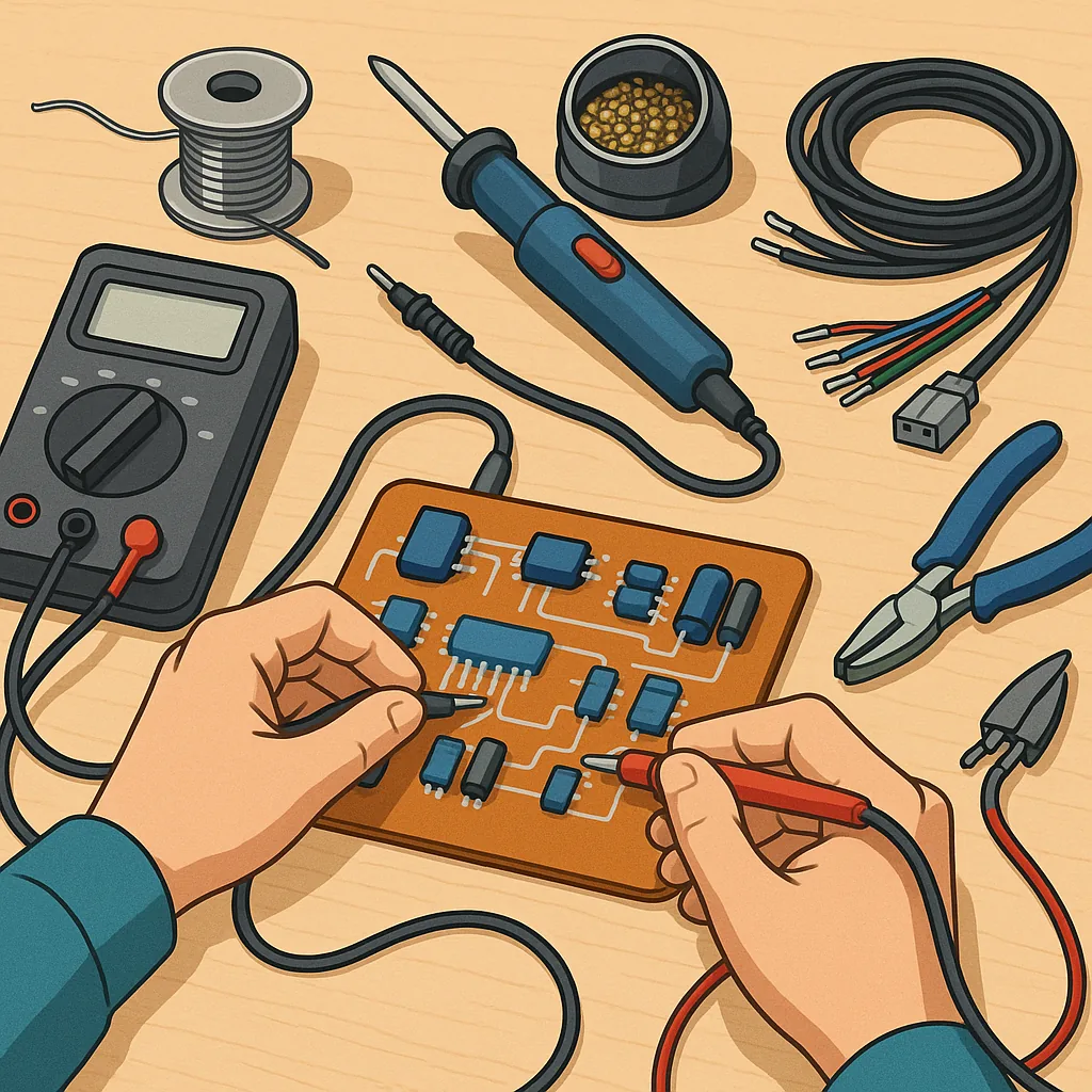
Gathering the right tools and taking simple safety precautions will speed diagnosis and reduce the risk of damage to components or the workspace. At minimum have a temperature‑regulated soldering iron, appropriate solder and flux, a multimeter, wire strippers, crimping pliers, and desoldering braid or a pump to hand. The following checklist is useful to run through before you begin work.
- Temperature‑controlled soldering iron with clean tips.
- Lead‑free or leaded solder of suitable diameter and flux suited to your workpiece.
- Desoldering braid or pump and a selection of tips and nozzles.
- Digital multimeter for continuity, diode and resistance checks.
- Wire strippers, ferrules, crimpers and heatshrink tubing.
- Magnifier or loupe, lint‑free cloth and isopropyl alcohol for cleaning.
Begin with a visual inspection because many failures are obvious under magnification, and this step is non‑invasive. Look for dull, grainy or cracked solder joints which suggest cold joints, visible solder bridges between pads, lifted or burnt pads which indicate excess heat, and frayed wire strands that no longer make good contact. On cable assemblies check for pinched insulation, exposed conductors and loose terminal screws. Note any discoloration or melted insulation as evidence of heat or overload and do not power test until these issues are addressed.
Use a multimeter to confirm continuity and to measure resistance where appropriate. For signal and ground traces you should expect near‑zero continuity; measure a known good sample on the same board type if available to set a baseline. For power rails check for unexpected shorts to ground and verify voltage levels under load where possible. A slow intermittent fault often shows as a variable resistance when you flex a wire or reheat a suspect joint, which points to a mechanical or cold solder joint instead of a component fault.
When you identify a poor solder joint, rework it rather than adding more solder immediately. Remove old solder with wick or a pump, clean the area with isopropyl alcohol, add a small amount of flux, and reflow with the correct temperature and tip for the pad size. Aim for good wetting between pad, trace and component lead so the solder forms a smooth concave fillet, and avoid excessive heat which can delaminate pads or damage sensitive parts. If a bridge has formed between pins, use solder wick and a clean tip to remove the bridge and then apply fresh solder sparingly.
Wiring reliability often depends as much on mechanical strain relief and correct termination as on the solder joint itself. Avoid soldering bare stranded wire directly into screw terminals where strands can work loose; use ferrules or proper crimp terminals where possible. Be cautious with tinning stranded wire because solder can creep and break under flex; use ferrules to maintain strand integrity. Route cables to avoid sharp bends and chafe points, secure them with cable ties or adhesive mounts, and use heatshrink for insulation and strain relief at joints and connectors.
Finish each repair with functional and environmental checks and a clear notation of what was done. Run the device through its normal operating conditions while watching for temperature rise, intermittent behaviour and unusual noise. For project inspiration, reference material and community examples see the Maker & DIY posts on this site for similar troubleshooting write‑ups and wiring techniques that you can adapt to your own builds. Regular practice, methodical testing and modest documentation will make basic soldering and wiring reliability much more predictable. For more builds and experiments, visit my main RC projects page.
Comments
Post a Comment