RC electronics troubleshooting: a step-by-step practical guide
When an RC model stops behaving as expected, a calm and methodical approach makes all the difference, and this tutorial will guide you through a reliable sequence of checks and simple repairs to get you flying, driving or sailing again safely and confidently.
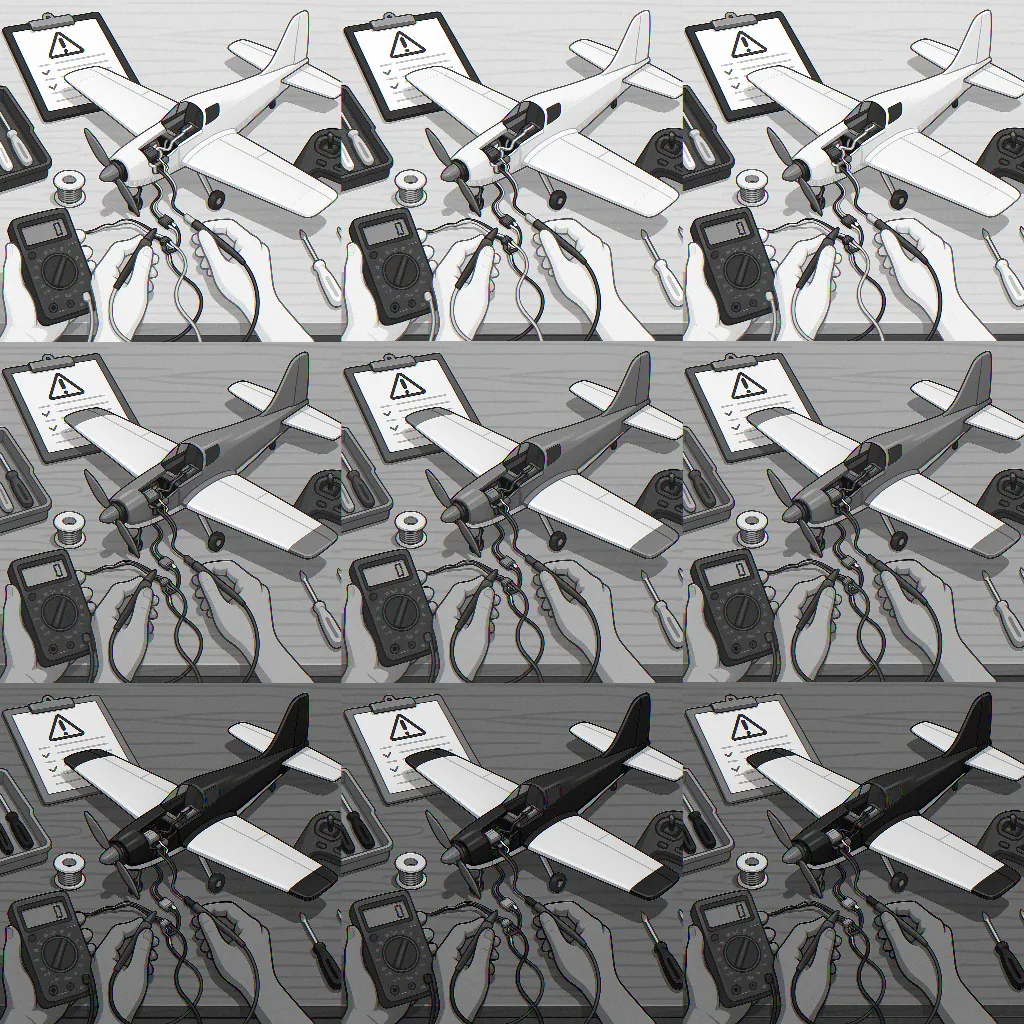
Start with safety and a basic visual inspection to avoid surprises, and always remove the prop, wheel or moving parts and disconnect the battery before touching electronics to prevent injury and damage. Check for obvious signs of trouble such as burnt components, melted insulation, loose solder joints, corrosion on connectors, bent pins and a lingering smell of electronics overheating. Note which parts were warm before power down and whether damage is localised to a single module or distributed across the model, as that observation will guide the following tests.
- Multimeter for voltage, continuity and resistance checks.
- Spare battery or a battery checker to verify cell health and charge under load.
- Servo tester or a simple receiver with a known-good transmitter to isolate control signals.
- Soldering iron, flux, spare connectors and heat-shrink for repairs.
- Small tools: tweezers, wire cutters, cable ties and a magnifier.
With tools ready, perform basic power and continuity checks using your multimeter, starting with the battery and power distribution. Measure the battery voltage at rest and under a short load to confirm capacity and sag behaviour. Check the continuity of main power leads and the resistance of any fuses or polyswitches. On brushless systems, verify the BEC or UBEC output voltage at the receiver rail and ensure it remains steady under applied load, because brownouts can cause intermittent control faults that mimic receiver or transmitter failure.
Next isolate the speed controller and motor, as many faults show up in this area; inspect ESC capacitors for bulging or leakage and check motor windings for continuity and balanced resistance between phases. If you suspect the ESC, try calibrating the throttle range and testing the motor with a servo tester or a known-good ESC, taking care to immobilise the drive train during bench tests. For brushed motors, check brushes and commutator cleanliness, and for brushless motors listen for bearings or rubbing that indicate mechanical distress rather than electrical failure.
Receiver and radio issues are another common source of frustration, so confirm the receiver is bound to the transmitter and that antenna placement is correct and undamaged. Test channels using a simple transmitter or a bench-bound receiver input to verify correct PWM, PPM or SBUS outputs, and examine the receiver's power rail for voltage dips when servos move. If you see jitter or dropouts, try a different receiver or move the antenna away from high-current wiring to rule out RF interference or poor grounding.
Servos and actuators can draw excessive current when mechanically obstructed so run each servo free of load and check for smooth movement and stable current draw, using your multimeter to observe stalls or spikes. Swap suspect servos with a known-good unit to confirm electrical integrity, and inspect connectors for bent pins, loose crimps or corrosion before replacing them. Re-solder any questionable joints, use fresh shrink tubing and ensure that signal, power and ground lines are not subject to shorts caused by sharp edges or damp conditions.
Finish with a systematic reassembly and staged testing procedure so you only apply full power once every subsystem passes its bench tests, and keep a simple log of which parts you replaced or swapped to make diagnosing persistent faults easier on subsequent troubleshooting sessions. If you need more projects or reference material in the same practical vein, take a look at the Maker & DIY tag page for related posts that may help with parts, tools and workflow optimisation. For more builds and experiments, visit my main RC projects page.
Comments
Post a Comment