RC electronics troubleshooting: practical tips and tricks for makers
When your radio-controlled model stops responding or behaves unpredictably, it can be tempting to panic and replace parts unnecessarily, but careful RC electronics troubleshooting usually identifies the real fault quickly and keeps costs down. This guide collects practical checks and habits that hobbyists and makers can apply in the workshop or at the field to diagnose common failures without guesswork.
Begin with a safety and basic sanity check routine before you touch components, because many faults are caused by simple issues that mimic complex failures. Ensure the battery is at a safe voltage for handling and that propellers or rotors are removed or restrained when powering systems. Check that the transmitter and receiver are on the same protocol and that the model is within a clear line of sight for initial tests. Use a fresh set of charged batteries in the transmitter as a first step, because low transmitter voltage is a frequent cause of apparent receiver failure.
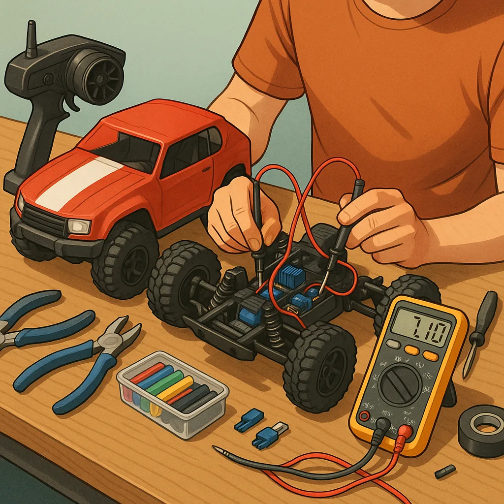
Power systems are the most common source of problems, so make those your primary focus in early troubleshooting. Measure battery pack voltage under load with a multimeter and verify that connectors and wiring do not show signs of heating or corrosion. Confirm that any battery eliminator circuits or voltage regulators provide the correct output for the receiver and servos, and watch for voltage sag when motors are engaged. If you suspect an intermittent supply, try substituting a known-good battery or supply to see if the symptoms vanish, and keep the ESC in view for fault LED codes if applicable.
RF and control signal problems often present as jittery or unresponsive controls, and they can be subtle to isolate. Check antenna routing on the receiver to ensure it is not lying directly against carbon fibre or metal parts that shield signals, and try relocating the receiver within the airframe to improve spacing from noise sources. Bind the receiver to the transmitter again and test with a simple setup such as a bench-mounted servo to exclude mechanical friction. For models with telemetry or digital servos, test one system at a time to see whether a specific device introduces interference or unexpected load behaviour.
- Quick checks to reduce diagnostic time include: confirming basic transmitter battery health, observing LED status codes on ESC and receiver, swapping a single servo or ESC with a known-good unit, isolating one subsystem at a time, and using a receiver tester or servo tester if available.
Electrical noise and ground loops can produce mysterious symptoms, so good practice in wiring and soldering pays dividends when troubleshooting. Keep signal and power wires routed separately where possible, use twisted pairs for motor wires if not using shielded cables, and secure all connections with proper solder joints or quality crimp connectors to avoid intermittent contact. If you have an oscilloscope, probe the supply rails for spikes when motors are engaged; if not, a small ceramic capacitor across motor leads and a decoupling capacitor near the receiver supply can often stabilise the system in a low-cost manner.
A methodical approach saves time: document each change and test the model under the same conditions after each modification so you can identify which action resolved the issue or changed behaviour. Photograph connector orientations and label wires if you disassemble components, because a miswired plug can mimic a component failure. If a component must be replaced, try to swap only one item at a time and retest before discarding the faulty part, because sometimes a replacement reveals a secondary issue that was masked by the original fault. For ongoing reference and community tips, you can find related Maker & DIY posts on the Build & Automate site at the Maker & DIY label.
Finally, cultivate a small set of tools and spares that suit your usual models, such as a reliable multimeter, quality soldering iron, servo tester, small assortment of connectors, and a few common spare servos and ESCs. Regular maintenance—cleaning connectors, reflowing suspect solder joints, and checking motor bearings—prevents many field failures. Systematic RC electronics troubleshooting combined with good workshop habits will get your model back flying or driving with minimal downtime and less frustration. For more builds and experiments, visit my main RC projects page.
Comments
Post a Comment